Most of the time, using conventional graphic techniques is the right way to go. Sometimes, though, experimentation and creativity at the fundamental levels of an effect can be beneficial to the style of the game, making it stand out more. In this tutorial I’m going to show you how to create an animated 2D lava river using Bézier curves, custom textured geometry and vertex shaders.
Note: Although this tutorial is written using AS3 and Flash, you should be able to use the same techniques and concepts in almost any game development environment.
Final Result Preview
Click the Plus sign to open more options: you can adjust the thickness and speed of the river, and drag the control points and position points around.
No Flash? Check out the YouTube video instead:
The actual demo runs at a much higher framerate.
Setup
The demo implementation above uses AS3 and Flash with Starling Framework for GPU accelerated rendering and the Feathers library for UI elements. In our initial scene we are going to place a ground image and a foreground rock image. Later we are going to add a river, inserting it between those two layers.
Geometry
Rivers are formed by complex natural processes of interaction between a fluid mass and the ground beneath it. It would be impractical to do a physically correct simulation for a game. We just want go get the right visual representation, and to do so we are going to use a simplified model of a river.
Modeling the river as a curve is one of the solutions we can use, enabling us to have a good control and achieve a meandering look. I chose to use quadratic Bézier curves to keep things simple.
Bézier curves parametric curves often used in computer graphics; in quadratic Bézier curves, the curve passes through two specified points, and its shape is determined by the third point, which is usually called a control point.
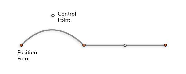
As shown above, the curve passes through the position points while the control point manages the course it takes. For example, putting the control point directly between the position points defines a straight line, while other values for the control point “attract” the curve to go near that point.
This type of curve is defined using the following mathematical formula:
At t=0 we are at the start of our curve; at t=1 we are at the end.
Technically we are going to use multiple Bézier curves where the end of one is the start of the other, forming a chain.
Now we have to solve the problem of actually displaying our river. Curves have no thickness, so we are going to build a geometric primitive around it.
First we need a way to take curve and convert it into line segments. In order to do this we take our points and plug them in the mathematical definition of the curve. The neat thing about this is that we can easily add a parameter to control the quality of this operation.
Here’s the code to generate the points from the definition of the curve:
// Calculate point from quadratic Bezier expression
private function quadraticBezier(P0:Point, P1:Point, C:Point, t:Number):Point
{
    var x = (1 - t) * (1 - t) * P0.x + (2 - 2 * t) * t * C.x + t * t * P1.x;
    var y = (1 - t) * (1 - t) * P0.y + (2 - 2 * t) * t * C.y + t * t * P1.y;
    return new Point(x, y);
}
And here’s how to convert the curve to line segments:
// This is a method which uses a list of nodes
// Each node is defined as: {position, control}
public function convertToPoints(quality:Number = 10):Vector.
{
    var points:Vector. = new Vector.();
    var precision:Number = 1 / quality;
    // Pass through all nodes to generate line segments
    for (var i:int = 0; i < _nodes.length - 1; i++)
    {
        var current:CurveNode = _nodes[i];
        var next:CurveNode = _nodes[i + 1];
        // Sample Bezier curve between two nodes
        // Number of steps is determined by quality parameter
        for (var step:Number = 0; step < 1; step += precision)
        {
            var newPoint:Point = quadraticBezier(current.position,
                next.position, current.control, step);
            points.push(newPoint);
        }
    }
    return points;
}
We can now take an arbitrary curve and convert it into a custom number of line segments – the more segments, the higher the quality:
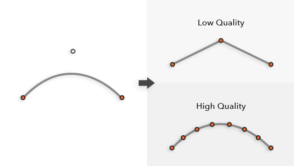
To get to the geometry we’re going generate two new curves based on the original one. Their position and control points will be moved by a normal vector offset value, which we can think of as the thickness. The first curve will be moved in the negative direction, while second is moved in the positive direction.
We’ll now use the function defined earlier to create line segments form the curves. This will form a boundary around the original curve.
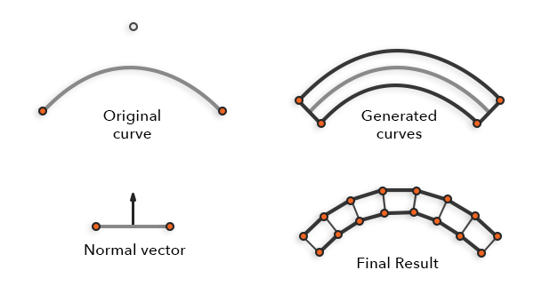
How do we do this in code? We’ll need to calculate normals for position and control points, multiply them by the offset and add them to the original values. For the position points we’ll have to interpolate normals formed by lines to adjacent control points.
// Iterate through all points
for (var i:int = 0; i < _nodes.length; i++) {
    var normal:Point;
    var surface:Point;  // Normal formed by position points
    if (i == 0) {
        // First point - take normal from first line segment
        normal = lineNormal(_nodes[i].position, _nodes[i].control);
        surface = lineNormal(_nodes[i].position, _nodes[i + 1].position);
    }
    else if (i + 1 == _nodes.length) {
        // Last point - take normal from last line segment
        normal = lineNormal(_nodes[i - 1].control, _nodes[i].position);
        surface = lineNormal(_nodes[i - 1].position, _nodes[i].position);
    }
    else {
        // Middle point - take 2 normals from segments
        // adjecent to the point, and interpolate them
        normal = lineNormal(_nodes[i].position, _nodes[i].control);
        normal = normal.add(
            lineSegmentNormal(_nodes[i - 1].control, _nodes[i].position));
        normal.normalize(1);
        // This causes a slight visual issue for thicker rivers
        // It can be avoided by adding more nodes
        surface = lineNormal(_nodes[i].position, _nodes[i + 1].position);
    }
    // Add offsets to the original node, forming a new one.
    nodesWithOffset.add(
        _nodes[i].position.x + normal.x * offset,
        _nodes[i].position.y + normal.y * offset,
        _nodes[i].control.x + surfaceNormal.x * offset,
        _nodes[i].control.y + surfaceNormal.y * offset
    );
}
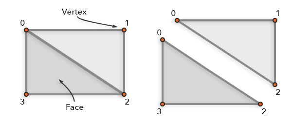
You can already see that we can use those points to define small four sided polygons – “quads”. Our implementation uses a custom Starling DisplayObject, which gives our geometric data directly to the GPU.
One problem, depending on the implementation, is that we can’t send quads directly; instead, we have to send triangles. But it’s easy enough to pick out two triangles using four points:
Result:
Texturing
Clean geometric style is fun, and it might even be a good style for some experimental games. But, to make our river look really good we could do with a few more details. Using a texture is a good idea. Which leads us to the problem of displaying it on custom geometry created earlier.
We’ll have to add additional information to our vertices; positions alone won’t do anymore. Each vertex can store additional parameters to our liking, and to support texture mapping we will need to define texture coordinates.
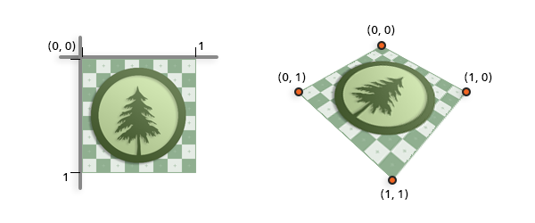
Texture coordinates are in texture space, and map pixel values of the image to the world positions of vertices. For each pixel that appears on the screen, we calculate interpolated texture coordinates and use them to lookup pixel values for positions in the texture. Values 0 and 1 in texture space correspond to texture edges; if values leave that range we have a couple of options:
- Repeat – indefinitely repeat the texture.
- Clamp – cut off the texture outside bounds of interval [0, 1].
Those who know a little bit about texture mapping are certainly aware of possible complexities of the technique. I have good news for you! This way of representing rivers is easily mapped to a texture.
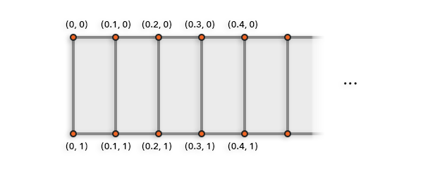
From the sides texture height is mapped in its entirety, while the length of the river is segmented into smaller chunks of the texture space, appropriately sized to texture width.
Now to implement it in the code:
// _texture is a Starling texture
var distance:Number = 0;
// Iterate through all points
for (var i:int = 0; i < _points.length; i++) {          if (i > 0) {
        // Distance in texture space for current line segment
        distance += Point.distance(lastPoint, _points[i]) / _texture.width;
    }
    // Assign texture coordinates to geometry
    _vertexData.setTexCoords(vertexId++, distance, 0);
    _vertexData.setTexCoords(vertexId++, distance, 1);
}
Now it looks a lot more like a river:
Animation
Our river now looks a lot more like a real one, with one big exception: it’s standing still!
Okay, so we need to animate it. The first thing that you may think of is to use sprite sheet animation. And that may well work, but in order to keep more flexibility and save a bit on texture memory, we’ll do something more interesting.
Instead of changing the texture, we can change the way the texture maps to the geometry. We do this by changing texture coordinates for our vertices. This will only work for tileable textures with mapping set to repeat.

An easy way to implement this is to change the texture coordinates on the CPU and send the results to the GPU every frame. That’s usually a good way to start an implementation this kind of technique, since debugging is much easier. However, we are going to dive straight into the best way we can accomplish this: animating texture coordinates using vertex shaders.
From experience I can tell that people are sometimes intimidated by shaders, probably because of their connection to the advanced graphical effects of blockbuster games. Truth be told the concept behind them is extremely simple, and if you can write a program, you can write a shader – that’s all they are, small programs running on the GPU. We are going to use a vertex shader to animate our river, there are several other types of shaders, but we can do without them.
As the name implies, vertex shaders process vertices. They run for every vertex, and take as an input vertex attributes: position, texture coordinates and color.
Our goal is to offset the X value of river’s texture coordinate to simulate flow. We keep a flow counter and increase it every frame by time delta. We can specify an additional parameter for speed of the animation. Offset value should be passed to the shader as an uniform (constant) value, a way to provide shader program with more information than just vertices. This value is usually a four-component vector; we are just going to use the X component to store the value, while setting Y, Z, and W to 0.
// Texture offset at index 5, which we later reference in the shader
context.setProgramConstantsFromVector(Context3DProgramType.VERTEX, 5,
    new [-_textureOffset, 0, 0, 0], 1);
This implementation uses the AGAL shader language. It can be a bit hard to understand, as it is an assembly like language. You can learn more about it here.
Vertex shader:
m44 op, va0, vc0 // Calculate vertex world position
mul v0, va1, vc4 // Calculate vertex color
// Add vertex texture coordinate (va2) and our texture offset constant (vc5):
add v1, va2, vc5
Animation in action:
Why Stop Here?
We are pretty much done, except that our river still looks unnatural. The plain cut between background and the river is a real eyesore. To solve this you can use an additional layer of the river, slightly thicker, and a special texture, which would overlay the river banks and cover the ugly transition.
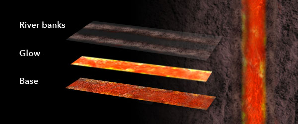
And since the demo represents river of molten lava, we can’t possibly go without a little glow! Make another instance of river geometry, now using a glow texture and set its blending mode to “add”. For even more fun, add smooth animation of the glow alpha value.
Final demo:
Of course, you can do a lot more than just rivers using this kind of effect. I’ve seen it used for ghost particle effects, waterfalls or even for animating chains. There is a lot of room for further improvement, performance wise final version from above can be done using one draw call if textures are merged to an atlas. Long rivers should be split into multiple parts and culled. A major extension would be to implement forking of curve nodes to enable multiple river paths and in turn simulate bifurcation.
I’m using this technique in our latest game, and I’m very pleased with what we can do with it. We are using it for rivers and roads (without animation, obviously). I’m thinking of using a similar effect for lakes.
Conclusion
I hope I gave you some ideas about how to think outside of regular graphic techniques, such as using sprite sheets or tile sets to accomplish effects like this. It requires a little bit more work, a little math, and some GPU programming knowledge, but in return you get much greater flexibility.