The Separating Axis Theorem is often used to check for collisions between two simple polygons, or between a polygon and a circle. As with all algorithms, it has its strengths and its weaknesses. In this tutorial, we’ll go over the math behind the theorem, and show how it can be used in game development with some sample code and demos.
Note: Although the demos and sourcecode of this tutorial use Flash and AS3, you should be able to use the same techniques and concepts in almost any game development environment.
What the Theorem States
The Separating Axis Theorem (SAT for short) essentially states if you are able to draw a line to separate two polygons, then they do not collide. It’s that simple.
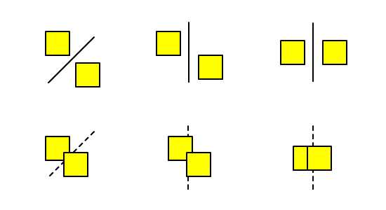
In the diagram above, you can easily see collisions occurring in the second row. However you try to squeeze a line in between the shapes, you will fail. The first row is exactly the opposite. You can easily draw a line to separate the shapes — and not just one line, but a lot of them:
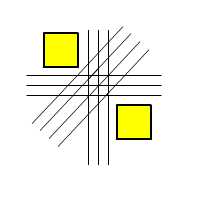
Okay, let’s not overdo this; I think you get the point. The key argument here is that if you can draw such a line, then there must be a gap separating the shapes. So how do we check for this?
Projection Along an Arbitrary Axis
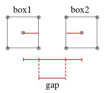
Let’s assume for now that the polygons we refer to are squares: box1 on the left and box2 on the right. It’s easy to see that these squares are horizontally separated. A straightforward approach to determine this in code is to calculate the horizontal distance between the two squares, then subtract the half-widths of box1 and box2:
//Pseudo code to evaluate the separation of box1 and box2
var length:Number = box2.x - box1.x;
var half_width_box1:Number = box1.width*0.5;
var half_width_box2:Number = box2.width*0.5;

var gap_between_boxes:Number = length - half_width_box1 - half_width_box2;
if(gap_between_boxes > 0) trace("It's a big gap between boxes")
else if(gap_between_boxes == 0) trace("Boxes are touching each other")
else if(gap_between_boxes < 0) trace("Boxes are penetrating each other")
What if the boxes are not oriented nicely?
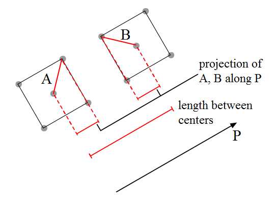
Although the evaluation of the gap remains the same, we’ll have to think of another approach to calculate the length between centers and the half-widths — this time along the P axis. This is where vector math comes in handy. We’ll project vectors A and B along P to get the half-widths.
Let’s do some math revision.
Vector Math Revision
We’ll start by recapping the definition of the dot product between two vectors A and B:
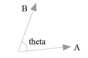
We can define the dot product using just the components of the two vectors:
\[
\begin{bmatrix}A_x \\A_y\end{bmatrix}.
\begin{bmatrix}B_x \\B_y\end{bmatrix}=
(A_x)(A_y)+(A_y)(B_y)
\]
Alternatively, we can understand the dot product using the magnitudes of the vectors and the angle between them:
\[
\begin{bmatrix}A_x \\A_y\end{bmatrix}.
\begin{bmatrix}B_x \\B_y\end{bmatrix}=
A_{magnitude}*B_{magnitude}*cos(theta)
\]
Now, let’s try to to figure out the projection of vector A onto P.
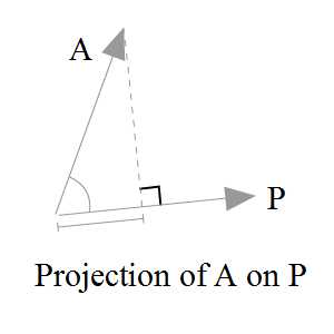
Referring to the diagram above, we know that the projection value is \(A_{magnitude}*cos(theta)\) (where theta is the angle between A and P). Although we can go ahead and calculate this angle to obtain the projection, it’s tricky. We need a more direct approach:
\[
A. P=A_{magnitude}*P_{magnitude}*cos(theta)\\
A.\frac{P}{P_{magnitude}}=A_{magnitude}*cos(theta)\\
\begin{bmatrix}A_x \\A_y\end{bmatrix}.
\begin{bmatrix}P_x/P_{magnitude} \\P_y/P_{magnitude}\end{bmatrix}=
A_{magnitude}*cos(theta)
\]
Note that \(\begin{bmatrix}P_x/P_{magnitude} \\P_y/P_{magnitude}\end{bmatrix}\) is actually the unit vector of P.
Now, instead of using the right side of the equation, as we were, we can opt for the left side and still arrive at the same result.
Application to a Scenario
Before we proceed, i’d like to clarify the naming convention used to denote the four corners of both boxes. This will be reflected in the code later:
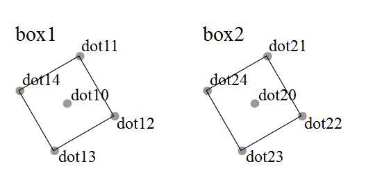
Our scenario is as below:
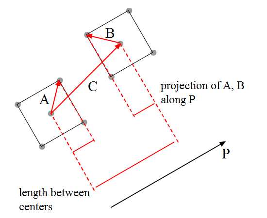
Let’s say both boxes are oriented 45° from the horizontal axis. We must calculate the following lengths in order to determine the gap between the boxes.
- Projection of A on axis P
- Projection of B on axis P
- Projection of C on axis P
Take special note of the arrows’ directions. While projection of A and C onto P will give a positive value, projection of B onto P will actually produce a negative value as the vectors are pointing in opposite directions. This is covered in line 98 of the AS3 implementation below:
var dot10:Point = box1.getDot(0);
var dot11:Point = box1.getDot(1);

var dot20:Point = box2.getDot(0);
var dot24:Point = box2.getDot(4);

//Actual calculations
var axis:Vector2d = new Vector2d(1, -1).unitVector;
var C:Vector2d = new Vector2d(
    dot20.x - dot10.x,
    dot20.y - dot10.y
)
var A:Vector2d = new Vector2d(
    dot11.x - dot10.x,
    dot11.y - dot10.y
)
var B:Vector2d = new Vector2d(
    dot24.x - dot20.x,
    dot24.y - dot20.y
)
var projC:Number = C.dotProduct(axis)
var projA:Number = A.dotProduct(axis);
var projB:Number = B.dotProduct(axis);

var gap:Number = projC - projA + projB;	//projB is expected to be a negative value
if (gap > 0) t.text = "There's a gap between both boxes"
else if (gap > 0) t.text = "Boxes are touching each other"
else t.text = "Penetration had happened."
Here’s a demo using the above code. Click and drag the red middle dot of both boxes and see the interactive feedback.
For the full source, check out DemoSAT1.as in the source download.
The Flaws
Well, we can go with the above implementation. But there are a few problems — let me point them out:
First, vectors A and B are fixed. So when you swap the positions of box1 and box2, the collision detection fails.
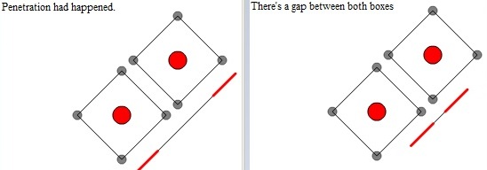
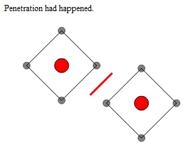
Second, we only evaluate the gap along one axis, so situations like the one below will not be evaluated correctly:
Although the previous demo is flawed, we did learn from it the concept of projection. Next, let’s improve on it.
Solving the First Flaw
So first of all, we’ll need to get the minimum and maximum projections of corners (specifically the vectors from the origin to the boxes’ corners) onto P.
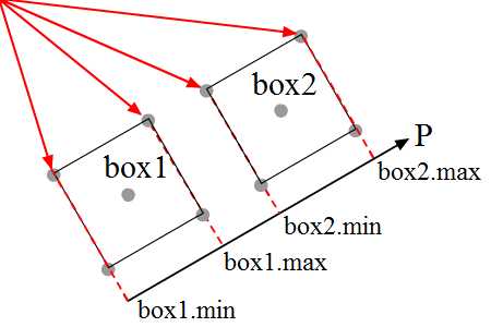
The diagram above shows the projection of the minimum and maximum corners onto P when the boxes are oriented nicely along P.
But what if box1 and box2 are not oriented accordingly?
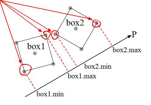
The diagram above shows boxes which are not neatly oriented along P, and their corresponding min-max projections. In this situation, we’ll have to loop through each corner of each box and select the correct ones as appropriate.
Now that we have the min-max projections, we’ll evaluate whether the boxes are colliding with each other. How?
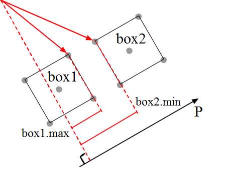
By observing the diagram above, we can clearly see the geometrical representation for projection of box1.max and box2.min onto axis P.
As you can see, when the’s a gap between the two boxes, box2.min-box1.max will be more than zero — or in other words, box2.min > box1.max. When the position of the boxes are swapped, then box1.min > box2.max implies there’s a gap between them.
Translating this conclusion into code, we get:
//SAT: Pseudocode to evaluate the separation of box1 and box2
if(box2.min>box1.max || box1.min>box2.max){
	trace("collision along axis P happened")
}
else{
	trace("no collision along axis P")
}
Initial Code
Let’s look at some more detailed code for figuring this out. Note that the AS3 code here is not optimised. Although it’s long and descriptive, the advantage is that you can see how the math behind it works.
First of all, we need to prepare the vectors:
//preparing the vectors from origin to points
//since origin is (0,0), we can conveniently take the coordinates
//to form vectors
var axis:Vector2d = new Vector2d(1, -1).unitVector;
var vecs_box1:Vector.<Vector2d> = new Vector.<Vector2d>;
var vecs_box2:Vector.<Vector2d> = new Vector.<Vector2d>;

for (var i:int = 0; i < 5; i++) {
    var corner_box1:Point = box1.getDot(i)
    var corner_box2:Point = box2.getDot(i)

    vecs_box1.push(new Vector2d(corner_box1.x, corner_box1.y));
    vecs_box2.push(new Vector2d(corner_box2.x, corner_box2.y));
}
Next, we obtain the min-max projection on box1. You can see a similar approach used on box2:
//setting min max for box1
var min_proj_box1:Number = vecs_box1[1].dotProduct(axis);
var min_dot_box1:int = 1;
var max_proj_box1:Number = vecs_box1[1].dotProduct(axis);
var max_dot_box1:int = 1;

for (var j:int = 2; j < vecs_box1.length; j++)
{
    var curr_proj1:Number = vecs_box1[j].dotProduct(axis)
    //select the maximum projection on axis to corresponding box corners
    if (min_proj_box1 > curr_proj1) {
        min_proj_box1 = curr_proj1
        min_dot_box1 = j
    }
    //select the minimum projection on axis to corresponding box corners
    if (curr_proj1> max_proj_box1) {
        max_proj_box1 = curr_proj1
        max_dot_box1 = j
    }
}
Finally, we evaluate whether there’s a collision on that specific axis, P:
var isSeparated:Boolean = max_proj_box2 < min_proj_box1 || max_proj_box1 < min_proj_box2
if (isSeparated) t.text = "There's a gap between both boxes"
else t.text = "No gap calculated."
Here’s a demo of the implementation above:
You may drag either box around via its middle point, and rotate it with the R and T keys. The red dot indicates the maximum corner for a box, while yellow indicates the minimum. If a box is aligned with P, you may find that these dots flicker as you drag, as those two corners share the same characteristics.
Check out the full source in DemoSAT2.as in the source download.
Optimisation
If you’d like to speed up the process, there’s no need to calculate for the unit vector of P. You can therefore skip quite a number of expensive Pythagoras’s theorem calculations which involve Math.sqrt():
\( \begin{bmatrix}A_x \\A_y\end{bmatrix}.
\begin{bmatrix}P_x/P_{magnitude} \\P_y/P_{magnitude}\end{bmatrix}=
A_{magnitude}*cos(theta)
\)
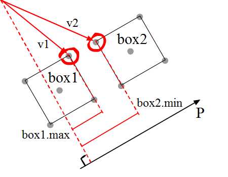
The reasoning is as follows (refer to diagram above for some visual guidance on variables):
/*
Let:
P_unit be the unit vector for P,
P_mag be P's magnitude,
v1_mag be v1's magnitude,
v2_mag be v2's magnitude,
theta_1 be the angle between v1 and P,
theta_2 be the angle between v2 and P,

Then:
box1.max < box2.min
=> v1.dotProduct(P_unit) < v2.dotProduct(P_unit)
=> v1_mag*cos(theta_1) < v2_mag*cos(theta_2)
*/
Now, mathematically, the sign of inequality remains the same if both sides of the inequality are multiplied by the same number, A:
/*
So:
A*v1_mag*cos(theta_1) < A*v2_mag*cos(theta_2)

If A is P_mag, then:
P_mag*v1_mag*cos(theta_1) < P_mag*v2_mag*cos(theta_2)
...which is equivalent to saying:
v1.dotProduct(P) < v2.dotProduct(P)
*/
So whether it’s a unit vector or not doesn’t actually matter — the result is the same.
Do bear in mind that this approach is useful if you are checking for overlap only. To find the exact penetration length of box1 and box2 (which for most games you’ll probably need to), you still need to calculate the unit vector of P.
Solving the Second Flaw
So we solved the issue for one axis, but that’s not the end of it. We still need to tackle other axes — but which?
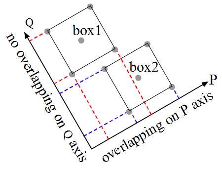
The analysis for boxes is quite straightforward: we compare two axes P and Q. In order to confirm a collision, overlapping on all axes has to be true — if there’s any axis without an overlap, we can conclude that there’s no collision.
What if the boxes are oriented differently?
Click the green button to turn to another page. So of the P, Q, R, and S axes, there’s only one axis that shows no overlapping between boxes, and our conclusion is that there’s no collision between the boxes.
But the question is, how do we decide which axes to check for overlapping? Well, we take the normals of the polygons.
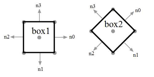
In a generalised form, with two boxes, we’ll have to check along eight axes: n0, n1, n2 and n3 for each of box1 and box2. However, we can see that the following lie on the same axes:
n0andn2ofbox1n1andn3ofbox1n0andn2ofbox2n1andn3ofbox2
So we don’t need to go through all eight; just four will do. And if box1 and box2 share the same orientation, we can further reduce to only evaluate two axes.
What about for other polygons?
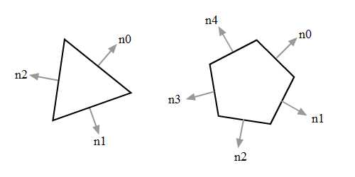
Unfortunately, for the triangle and pentagon above there’s no such shortcut, so we’ll have to run checks along all normals.
Calculating Normals
Each surface has two normals:
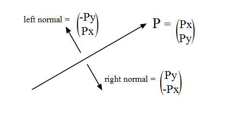
The diagram above shows the left and right normal of P. Note the switched components of the vector and the sign for each.
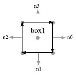
For my implementation, I’m using a clockwise convention, so I use the left normals. Below is an extract of SimpleSquare.as demonstrating this.
public function getNorm():Vector.<Vector2d> {
    var normals:Vector.<Vector2d> = new Vector.<Vector2d>
    for (var i:int = 1; i < dots.length-1; i++)
    {
        var currentNormal:Vector2d = new Vector2d(
            dots[i + 1].x - dots[i].x,
            dots[i + 1].y - dots[i].y
        ).normL	//left normals
        normals.push(currentNormal);
    }
    normals.push(
        new Vector2d(
            dots[1].x - dots[dots.length-1].x,
            dots[1].y - dots[dots.length-1].y
        ).normL
    )
    return normals;
}
New Implementation
I’m sure you can find a way to optimise the following code. But just so that we all get a clear idea of what’s happening, I’ve written everything out in full:
//results of P, Q
var result_P1:Object = getMinMax(vecs_box1, normals_box1[1]);
var result_P2:Object = getMinMax(vecs_box2, normals_box1[1]);
var result_Q1:Object = getMinMax(vecs_box1, normals_box1[0]);
var result_Q2:Object = getMinMax(vecs_box2, normals_box1[0]);

//results of R, S
var result_R1:Object = getMinMax(vecs_box1, normals_box2[1]);
var result_R2:Object = getMinMax(vecs_box2, normals_box2[1]);
var result_S1:Object = getMinMax(vecs_box1, normals_box2[0]);
var result_S2:Object = getMinMax(vecs_box2, normals_box2[0]);

var separate_P:Boolean = result_P1.max_proj < result_P2.min_proj ||
                         result_P2.max_proj < result_P1.min_proj
var separate_Q:Boolean = result_Q1.max_proj < result_Q2.min_proj ||
                         result_Q2.max_proj < result_Q1.min_proj
var separate_R:Boolean = result_R1.max_proj < result_R2.min_proj ||
                         result_R2.max_proj < result_R1.min_proj
var separate_S:Boolean = result_S1.max_proj < result_S2.min_proj ||
                         result_S2.max_proj < result_S1.min_proj

//var isSeparated:Boolean = separate_p || separate_Q || separate_R || separate_S
if (isSeparated) t.text = "Separated boxes"
else t.text = "Collided boxes."
You’ll see that some of the variables aren’t necessarily calculated to reach the result. If any one of separate_P, separate_Q, separate_R and separate_S is true, then they are separated and there’s no need to even proceed.
This means we can save a fair amount of evaluation, just by checking each of those Booleans after they’ve been calculated. It would require rewriting the code, but I think you can work your way through it (or check out the commented block in DemoSAT3.as).
Here’s a demo of the above implementation. Click and drag the boxes via their middle dots, and use the R and T keys to rotate the boxes:
Afterthoughts
When this algorithm is run, it checks through the normal axes for overlappings. I have two observations here to point out:
- SAT is optimistic that there’ll be no collision between polygons. The algorithm can exit and happily conclude “no collision” once any axis shows no overlapping. If there were any collision, SAT will have to run through all the axes to reach that conclusion — thus, the more collisions there actually are, the worse the algorithm performs.
- SAT uses the normal of each of the polygons’ edges. So the more complex the polygons are, the more expensive SAT will become.
Hexagon-Triangle Collision Detection
Here’s another sample code snippet to check for a collision between a hexagon and a triangle:
private function refresh():void {
//prepare the normals
var normals_hex:Vector.<Vector2d> = hex.getNorm();
var normals_tri:Vector.<Vector2d> = tri.getNorm();

var vecs_hex:Vector.<Vector2d> = prepareVector(hex);
var vecs_tri:Vector.<Vector2d> = prepareVector(tri);
var isSeparated:Boolean = false;

//use hexagon's normals to evaluate
for (var i:int = 0; i < normals_hex.length; i++)
{
    var result_box1:Object = getMinMax(vecs_hex, normals_hex[i]);
    var result_box2:Object = getMinMax(vecs_tri, normals_hex[i]);

    isSeparated = result_box1.max_proj < result_box2.min_proj || result_box2.max_proj < result_box1.min_proj
    if (isSeparated) break;
}
//use triangle's normals to evaluate
if (!isSeparated) {
    for (var j:int = 1; j < normals_tri.length; j++)
    {
        var result_P1:Object = getMinMax(vecs_hex, normals_tri[j]);
        var result_P2:Object = getMinMax(vecs_tri, normals_tri[j]);

        isSeparated = result_P1.max_proj < result_P2.min_proj || result_P2.max_proj < result_P1.min_proj
        if (isSeparated) break;
    }
}

if (isSeparated) t.text = "Separated boxes"
else t.text = "Collided boxes."
}
For the full code, check out DemoSAT4.as in the source download.
The demo is below. Interaction is the same as in previous demos: drag via the middle points, and use R and T to rotate.
Box-Circle Collision Detection
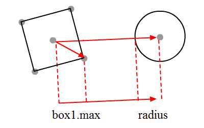
Collision with a circle may be one of the simpler ones. Because its projection is the same in all directions (it’s simply the circle’s radius), we can just do the following:
private function refresh():void {
    //prepare the vectors
    var v:Vector2d;
    var current_box_corner:Point;
    var center_box:Point = box1.getDot(0);

    var max:Number = Number.NEGATIVE_INFINITY;
    var box2circle:Vector2d = new Vector2d(c.x - center_box.x, c.y - center_box.y)
    var box2circle_normalised:Vector2d = box2circle.unitVector

    //get the maximum
    for (var i:int = 1; i < 5; i++)
    {
        current_box_corner = box1.getDot(i)
        v = new Vector2d(
            current_box_corner.x - center_box.x ,
            current_box_corner.y - center_box.y);
        var current_proj:Number = v.dotProduct(box2circle_normalised)

        if (max < current_proj) max = current_proj;
    }
    if (box2circle.magnitude - max - c.radius > 0) t.text = "No Collision"
    else t.text = "Collision"
}
Check out the full source in DemoSAT5.as. Drag either the circle or box to see them collide.
Conclusion
Well, that’s it for now. Thanks for reading and do leave your feedback with a comment or question. See you next tutorial!