You’re never too old for a game of Spot the Difference – I remember playing it as a kid, and I now find my wife still plays it occasionally! In this tutorial, we’ll look at how to detect when a ring has been drawn around an object, with an algorithm that could be used with mouse, stylus, or touchscreen input.
Note: Although the demos and sourcecode of this tutorial use Flash and AS3, you should be able to use the same techniques and concepts in almost any game development environment.
Final Result Preview
Let’s take a look at the final result we will be working towards. The screen is divided into two images, which are almost identical but not quite. Try to spot the six differences, and circle those on the left image. Good luck!
Note: You do not have to draw a perfect circle! You only need to draw a rough ring or loop around each difference.
Don’t have Flash? Check out this video demo:
Step 1: The Circling Motion
We’ll be using some vector calculations in the algorithm. As always, it’s good to understand the underlying math before applying it, so here’s a brief refresher of vector math.
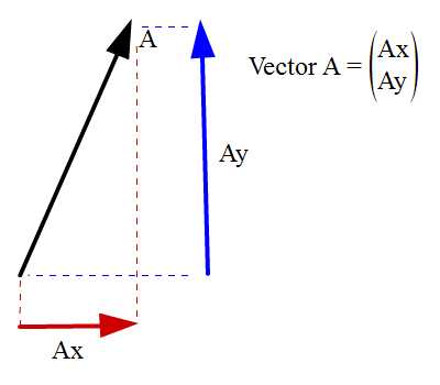
The image above shows the vector A broken down to its horizontal and vertical components (Ax and Ay, respectively).
Now let’s look at the dot product operation, illustrated in the image below. First, you will see the dot product operation between vectors A and B.
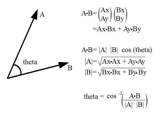
To find the angle sandwiched between the two vectors, we can make use of this dot product.
|A| and |B| denote the magnitudes of vectors A and B, so given |A| and |B| and A dot B, what’s left unknown is theta. With a little algebra (shown in the image), the final equation is produced, which we can use to find theta.
For more information on vector dot product, do refer to the following Wolfram page.
The other useful operation is cross product. Check out the operation below:

This operation is useful to find whether the sandwiched angle is clockwise or counter-clockwise relative to a specific vector.
Let me elaborate further. For the case of the diagram above, rotation from A to B is clockwise, so A cross B is negative. Rotation of B to A is counter-clockwise, so B cross A is positive. Note that this operation is sequence sensitive. A cross B will produce different result from B cross A.
That’s not all. It happens that in many game development platforms’ coordinate space, the y-axis is inverted (y increases as we move downwards). So our analysis is reversed, and A cross B will be positive while B cross A is negative.
That’s enough revision. Let’s get to our algorithm.
Step 2: Circling Interaction
Players will have to circle the correct detail on the image. Now how do we do that? Before answering this question, we should calculate the angle between two vectors. As you’ll now remember, we can use the dot product for this, so we shall implement that equation here.
Here’s a demo to illustrate what we’re doing. Drag either arrow around to see the feedback.
Let’s see how this works. In the code below, I’ve simply initialised the vectors and a timer, and put some interactive arrows on the screen.
public function Demo1()
{
    feedback = new TextField; addChild(feedback);
    feedback.selectable = false;
    feedback.autoSize = TextFieldAutoSize.LEFT;

    a1 = new Arrow; addChild(a1);
    a2 = new Arrow; addChild(a2); a2.rotation = 90

    center = new Point(stage.stageWidth >> 1, stage.stageHeight >> 1)
    a1.x = center.x;  a1.y = center.y; a1.name = "a1";
    a2.x = center.x;  a2.y = center.y; a2.name = "a2";

    a1.transform.colorTransform = new ColorTransform(0, 0, 0, 1, 255);
    a2.transform.colorTransform = new ColorTransform(0, 0, 0, 1, 0, 255);

    a1.addEventListener(MouseEvent.MOUSE_DOWN, handleMouse);
    a2.addEventListener(MouseEvent.MOUSE_DOWN, handleMouse);
    stage.addEventListener(MouseEvent.MOUSE_UP, handleMouse);

    v1 = new Vector2d(1, 0);
    v2 = new Vector2d(0, 1);
    curr_vec = new Vector2d(1, 0);

    t = new Timer(50);
}
Every 50 milliseconds, the function below is run, and used to update the graphical and text feedback:
private function update(e:TimerEvent):void
{
    var curr_angle:Number = Math.atan2(mouseY - center.y, mouseX - center.x);
    curr_vec.angle = curr_angle;

    if (item == 1) {
        //update arrow's rotation visually
        a1.rotation = Math2.degreeOf(curr_angle);

        //measuring the angle from a1 to b1
        v1 = curr_vec.clone();
        direction = v2.crossProduct(v1);
        feedback.text = "You are now moving the red vector, A \n";
        feedback.appendText("Angle measured from green to red: ");
    }
    else if (item == 2) {
        a2.rotation = Math2.degreeOf(curr_angle);

        v2 = curr_vec.clone();
        direction = v1.crossProduct(v2);
        feedback.text = "You are now moving the green vector, B\n";
        feedback.appendText("Angle measured from red to green: ");
    }

    theta_rad = Math.acos(v1.dotProduct(v2));	//theta is in radians
    theta_deg = Math2.degreeOf(theta_rad);
    if (direction < 0) {
        feedback.appendText("-" + theta_deg.toPrecision(4) + "\n");
        feedback.appendText("rotation is anti clockwise")
    }
    else {
        feedback.appendText(theta_deg.toPrecision(4) + "\n");
        feedback.appendText("rotation is clockwise")
    }
    drawSector();
}
You will notice that the magnitude for v1 and v2 are both 1 unit in this scenario (check out line 52 and 53 highlighted above), so I skipped the need to calculate the vectors’ magnitude for now.
If you want to see the full source code, check out Demo1.as in the source download.
Step 3: Detect a Full Circle
Ok, now that we have understood the basic idea, we’ll now use it to check whether the player successfully circled a point.
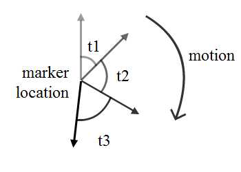
I hope the diagram speaks for itself. The start of the interaction is when the mouse button is pressed, and the end of the interaction is when the mouse button is released.
At every interval (of, say, 0.01 seconds) during the interaction, we’ll calculate the angle sandwiched between current and previous vectors. These vectors are constructed from the marker location (where the difference is) to the mouse location at that instance. Add up all these angles (t1, t2, t3 in this case) and if the angle made is 360 degrees at the end of interaction, then the player has drawn a circle.
Of course, you may tweak the definition of a full circle to be 300-340 degrees, giving room for player errors when performing mouse gesture.
Here’s a demo for this idea. Drag a circular gesture around the red marker in the middle. You can move the red marker’s position using W, A, S, D keys.
Step 4: The Implementation
Let’s examine the implementation for the demo. We’ll just look at the important calculations here.
Check out the highlighted code below and match it with the mathematical equation in Step 1. You will notice that the value for arccos sometimes produces Not a Number (NaN) if you skip line 92. Also, constants_value sometimes exceeds 1 due to rounding inaccuracies so we need to manually bring it back to a maximum of 1. Any input number for arccos more than 1 will produce a NaN.
private function update(e:TimerEvent):void
{
    graphics.clear();
    graphics.lineStyle(1)
    graphics.moveTo(marker.x, marker.y);
    graphics.lineTo(mouseX, mouseY);

    prev_vec = curr_vec.clone();
    curr_vec = new Vector2d(mouseX - marker.x, mouseY - marker.y);
    //value of calculation sometimes exceed 1 need to manually handle the precission
    var constants_value:Number = Math.min(1,
                                prev_vec.dotProduct(curr_vec) / (prev_vec.magnitude * curr_vec.magnitude)
                                );
    var delta_angle:Number = Math.acos(constants_value)	//angle made
    var direction:Number = prev_vec.crossProduct(curr_vec) > 0? 1: -1;	//checking the direction of rotation
    total_angle += direction * delta_angle;	//add to the cumulative angle made during the interaction
}
The full source for this can be found in Demo2.as
Step 5: The Flaw
One issue you may see is that as long as I draw a big circle enclosing the canvas, the marker will be considered circled. I don’t neccesarily need to know where the marker is.
Well, to counter this problem, we can check the proximity of the circular motion. If the circle is drawn within the confines of a certain range (the value of which is under your control), only then is it considered a success.
Check out the code below. If ever the user exceeds MIN_DIST (with a value of 60 in this case), then it’s considered a random guess.
private function update(e:TimerEvent):void
{
    graphics.clear();
    graphics.lineStyle(1)
    graphics.moveTo(marker.x, marker.y);
    graphics.lineTo(mouseX, mouseY);

    prev_vec = curr_vec.clone();
    curr_vec = new Vector2d(mouseX - marker.x, mouseY - marker.y);

    if (curr_vec.magnitude > MIN_DIST) within_bound = false;

    //value of calculation sometimes exceed 1 need to manually handle the precission
    var constants_value:Number = Math.min(1,
                                prev_vec.dotProduct(curr_vec) / (prev_vec.magnitude * curr_vec.magnitude)
                                );
    var delta_angle:Number = Math.acos(constants_value)	//angle made
    var direction:Number = prev_vec.crossProduct(curr_vec) > 0? 1: -1;	//checking the direction of rotation
    total_angle += direction * delta_angle;	//add to the cumulative angle made during the interaction

    mag_box.text = "Distance from marker: " + curr_vec.magnitude.toPrecision(4);
    mag_box.x = mouseX + 10;
    mag_box.y = mouseY + 10;
    feedback.text = "Do not go beyond "+MIN_DIST
}
Again, try to circle the marker. If you think the MIN_DIST is a little unforgiving, it can always be adjusted to suit the image.
Step 6: Different Shapes
What if the “difference” is not an exact circle? Some might be rectangular, or triangular, or any other shape.
In these cases, instead of using just one marker, we can put up a few:
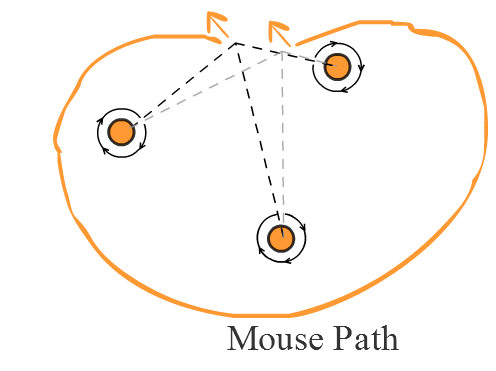
In the diagram above, two mouse cursors are shown at the top. Starting with the right-most cursor, we’ll make a circular clockwise motion to the other end on the left. Note that the path encircles all three markers.
I’ve also drawn the angles elapsed by this path on each of the markers (light dashes to dark dashes). If all three angles are more than 360 degrees (or whichever value you choose), only then do we count it as a circle.
But that’s not enough. Remember the flaw in Step 4? Well, the same goes here: we’ll need to check for proximity. Instead of requiring the gesture to not exceed a certain radius of a specific marker, we’ll just check whether the mouse cursor came close to all the markers for at least a short instance. I’ll use pseudo-code to explain this idea:
Calculate angle elapsed by path for marker1, marker2 and marker3

if each angle is more than 360
	if each marker's proximity was crossed by mouse cursor
		then the circle made is surrounding the area marked by markers
	endif
endif
Step 7: Demo for the Idea
Here, we’re using three dots to represent a triangle.
Try to circle around:
- one dot
- two dots
- three dots
…in the image below. Take note that the gesture only succeeds if it contains all three dots.
Let’s check out the code for this demo. I’ve highlighted the key lines for the idea below; the full script is in Demo4.as.
private function handleMouse(e:MouseEvent):void
{
    if (e.type == "mouseDown") {
        t.addEventListener(TimerEvent.TIMER, update);
        t.start();
        update_curr_vecs();
    }
    else if (e.type == "mouseUp") {
        t.stop();
        t.removeEventListener(TimerEvent.TIMER, update);

        //check if conditions were met
        condition1 = true	//all angles are meeting MIN_ANGLE
        condition2 = true	//all proximities are meeting MIN_DIST

        for (var i:int = 0; i < markers.length; i++) {
            if (Math.abs(angles[i])< MIN_ANGLE) {
                condition1 = false;
                break;
            }
            if (proximity[i] == false) {
                condition2 = false;
                break
            }
        }

        if (condition1 && condition2) {
            box.text="Attempt to circle the item is successful"
        }
        else {
            box.text="Failure"
        }

        reset_vecs();
        reset_values();
    }
}

private function update(e:TimerEvent):void
{
    update_prev_vecs();
    update_curr_vecs();
    update_values();
}
Step 8: Drawing the Circles
The best method for actually drawing the line that you trace will depend on your development platform, so I’ll just outline the method we would use in Flash here.
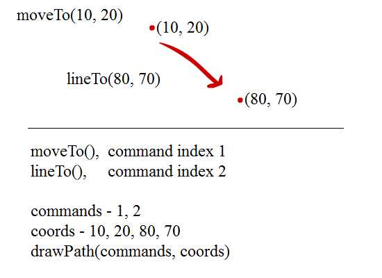
There are two ways to draw lines in AS3, as indicated by the image above.
The first approach is rather simple: use moveTo() to move the drawing position to coordinate (10, 20). Then draw a line to connect (10, 20) to (80, 70) using lineTo().
The second approach is to store all details in two arrays, commands[] and coords[] (with coordinates stored in (x, y) pairs within coords[]) and later draw all graphical details onto canvas using drawPath() in one single shot. I’ve opted for the second approach in my demo.
Check it out: try to click and drag the mouse on canvas to draw line.
And here’s the AS3 code for this demo. Check out the full source in Drawing1.as.
public class Drawing1 extends Sprite
{
    private var cmd:Vector.<int>;
    private var coords:Vector.<Number>;
    private var _thickness:Number = 2, _col:Number = 0, _alpha:Number = 1;

    public function Drawing1()
    {
        //assign event handlerst to mouse up and mouse down
        stage.addEventListener(MouseEvent.MOUSE_DOWN, mouseHandler);
        stage.addEventListener(MouseEvent.MOUSE_UP, mouseHandler);
    }

    /**
     * Mouse event handler
     * @param	e	mouse event
     */
    private function mouseHandler(e:MouseEvent):void
    {
        if (e.type == "mouseDown") {
            //randomise the line properties
            _thickness = Math.random() * 5;
            _col = Math.random() * 0xffffff;
            _alpha = Math.random() * 0.5 + 0.5

            //initiate the variables
            cmd = new Vector.<int>;
            coords = new Vector.<Number>;

            //first registration of line beginning
            cmd[0] = 1;
            coords[0] = mouseX;
            coords[1] = mouseY;

            //start the drawing when mouse move
            stage.addEventListener(MouseEvent.MOUSE_MOVE, mouseHandler);
        }
        else if (e.type == "mouseUp") {
            //remove the mouse move handler once mouse button is released
            stage.removeEventListener(MouseEvent.MOUSE_MOVE, mouseHandler);
        }
        else if (e.type == "mouseMove") {
            //pushing into the mouse move the
            cmd.push(2);			//draw command
            coords.push(mouseX);	//coordinates to draw line to
            coords.push(mouseY);
            redraw();				//execute the drawing command
        }
    }
    /**
     * Method to draw the line(s) as defined by mouse movement
     */
    private function redraw():void {
        graphics.clear();	//clearing all previous drawing
        graphics.lineStyle(_thickness, _col, _alpha);
        graphics.drawPath(cmd, coords);
    }

}
In Flash, using the graphics object for drawing like this uses retained mode rendering, meaning that the properties of the individual lines are stored separately – as opposed to immediate mode rendering, where only the final image is stored. (The same concepts exist in other development platforms; for instance, in HTML5, drawing to SVG uses retained mode, while drawing to canvas uses immediate mode.)
If there are many lines on screen, then storing and re-rendering them all separately may make your game slow and laggy. The solution to this will depend on your platform – in Flash, you can use BitmapData.draw() to store each line in a single bitmap after it has been drawn.
Step 9: Sample Level
Here I have created a demo for the sample level of a Spot the Difference game. Check it out! The full source is in Sample2.as of the source download.
Conclusion
Thanks for reading this article; I hope it gave you an idea for building your own game. Do leave some comments if there’s any issue with the code and I’ll get back to you as soon as possible.